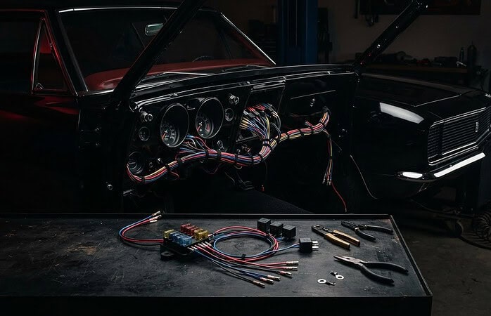

The wiring diagram is as important as the new display. A Dakota Digital gauges installation should start with the diagram for your specific vehicle, followed by mapping each connection to the gauge control module before routing cabin wiring. This preparation helps keep the classic dash tidy while giving the modern instruments the signals they need.
Finding the right wire can be the tricky part, especially when the speedometer signal, chassis ground, and tach connection aren’t immediately obvious. This reference explains how to use your vehicle-specific diagram to trace those connections, including where the speedometer signal is found on 1989-1991 trucks and how to approach the tach wire. Follow the wiring path before making connections, and treat each circuit as part of the complete system. The result is a clearer installation plan, with less guesswork between the original vehicle wiring and the new gauges.
Key Takeaways
- Use the wiring diagram for your specific vehicle to map circuits to the gauge control module before beginning cabin wiring.
- Trace the speedometer signal through the correct part of the instrument-panel harness for your truck’s model years.
- Plan the chassis ground as part of the system’s wiring path, not as an afterthought.
- Locate the tach lead near the distributor on TBI trucks, and route it carefully to keep the installation orderly.
Consulting the vehicle-specific wiring diagram
Start with the wiring diagram for your vehicle. Map its circuits to the gauge system before routing wires through the cabin.
Vehicle-Specific Wiring Diagrams and Manuals
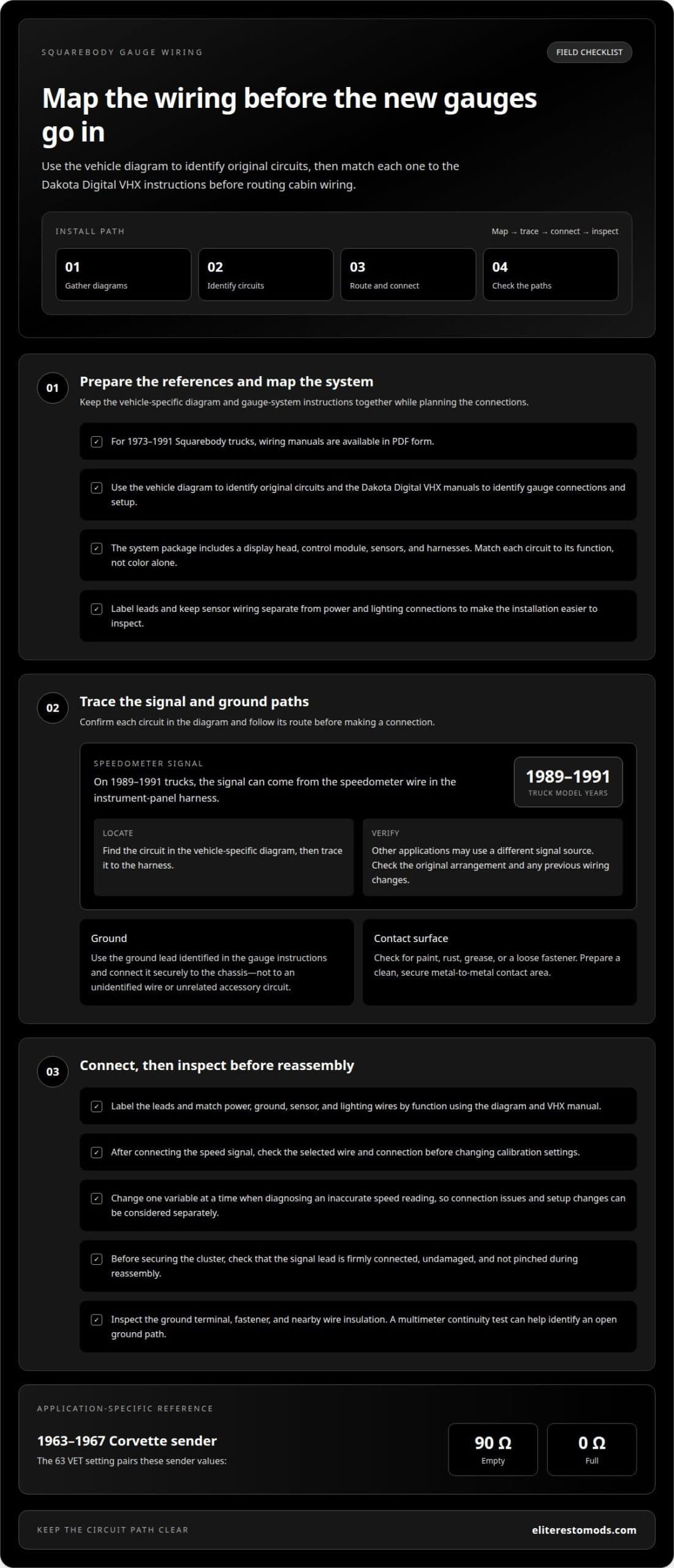
A vehicle-specific wiring diagram maps the circuits and connections for a particular vehicle. For 1973-1991 Squarebody trucks, wiring manuals are available in PDF form. Pair the vehicle diagram with the Dakota Digital VHX wiring and setup manuals: one identifies original circuits, the other shows gauge connections and setup. Planning a Dakota Digital gauges installation this way helps organize the work before wiring begins.
Aftermarket gauge brands can differ in their wiring and setup requirements. Compare the system instructions with your vehicle and its signals. Replacing gauges alone does not determine warranty, inspection, or emissions compliance; those depend on the vehicle and applicable requirements.
Power, Ground, Sensor, and Lighting Connections
These connections power the gauge system and carry its readings. A system package includes a display head, control module, sensors, and harnesses. Identify each circuit from the vehicle diagram, then match it to the VHX manual. Labeling leads and separating sensor wiring from power and lighting connections makes the installation easier to inspect.
Gather the manuals, supplied harnesses and sensors, hand tools suited to the cluster fasteners, and wire labels. Remove the factory cluster trim and fasteners, disconnect the plugs, then fit and connect the new cluster as directed in the manual. Match power, ground, sensor, and lighting wires by function, not color alone. Installation time varies with access, wiring condition, and setup needs. If a gauge behaves unexpectedly, inspect its connection and ground, then isolate that circuit before changing settings.
The forum provides wiring manuals in PDF form for 73 – 91 Squarebody trucks. Keep the relevant manual available while working, and use it to check planned connections against the vehicle diagram. Record any uncertainty rather than assuming a wire’s purpose from appearance; verify the circuit and its intended function before connecting it. This gives you a clear reference for reviewing your work and tracing a connection again if a gauge reading or lighting function needs attention.
Speedometer signal source
A speedometer signal is the input that lets the display register vehicle speed. On 1989-1991 trucks, the Dakota Digital speedometer signal can come from the speedometer wire in the instrument-panel harness. Locate that circuit in the vehicle-specific wiring diagram, then trace it to the harness before connecting the gauge lead. During a Dakota Digital gauges installation, wire identification should rely on the diagram and circuit path, not color alone.
That model-year detail gives truck owners a starting point, not a universal connection for every vehicle. Other applications may use a different signal source, so first identify the vehicle’s original speedometer arrangement. Check whether previous repairs or modifications changed the instrument-panel wiring. If the diagram and visible wiring do not align, pause and trace the circuit rather than tapping a nearby wire based on appearance.
Speedometer calibration aligns the gauge reading with the vehicle’s speed. First identify a suitable signal connection; calibration then configures how the display interprets that input. Follow the instructions for your specific system, since the procedure depends on its configuration.
After connecting the signal, assess the speed display against a consistent reference while the vehicle is moving. If the reading seems inaccurate, inspect the selected wire and connection before changing calibration settings. A loose connection and incorrect setup have different causes, so address them separately. During installation, change one variable at a time to pinpoint which adjustment affects the reading.
Before securing the cluster, inspect the signal lead for a firm connection and damage along its route. Confirm that it remains connected to the identified circuit and has not been pinched during reassembly. This final check helps maintain a clean signal path and simplifies later diagnosis.
For a 1963-1967 Corvette sender, the 63 VET setting corresponds to 90 ohms empty and 0 ohms full. In that stated setting, 90 ohms is the empty value, while 0 ohms is the full value. The sender description and the setting name identify the pairing; retain both values as given when referring to this application.
Chassis grounding
A chassis ground provides the electrical return path between the gauge system and the vehicle’s metal structure. Identify the ground lead in the Dakota Digital wiring instructions, then trace its route before installing the harness. Connect it securely to the chassis, not to an unidentified wire or unrelated accessory circuit.
Inspect the mounting area before fastening the ground terminal. Paint, rust, grease, or a loose fastener can interfere with metal-to-metal contact. For example, a painted dash brace may seem convenient, but it will not provide the same contact as a clean, secure surface. Prepare the connection area and fasten the terminal firmly without trapping it under trim or insulation.
Keep the gauge ground path distinct and easy to trace. If the wiring diagram identifies a designated ground connection, use it rather than choosing a nearby wire by appearance. Route the lead so it will not be pinched behind the instrument cluster or pulled tight when the dash is reassembled. Labeling the ground wire also simplifies later inspection.
Before reinstalling the cluster, inspect the connection between the gauge harness and chassis. Confirm that the terminal is seated, the fastener holds it securely, and the wire insulation is intact near the attachment. A multimeter continuity test can help identify an open ground path; follow the meter instructions and gauge-system manual for the procedure.
If a display behaves inconsistently after installation, check the ground connection before disturbing sensor or signal wiring. Look for a loose terminal, damaged lead, or contact against paint or corrosion. Then inspect the harness connection at the control module. Changing one connection at a time helps isolate the fault while preserving the rest of the carefully routed wiring.
Finding and connecting the tach wire
A tach wire carries the engine-speed signal to the tachometer. On TBI trucks, it is located near the distributor. Use the vehicle-specific wiring diagram to identify the correct lead before connecting it. Its location narrows the search, but trace the wire against the diagram rather than choosing one by appearance.
Keep the tach lead separate from other wires where practical. This makes the route easier to inspect and reduces confusion during installation or later troubleshooting. Start near the distributor, follow the identified wire path, and plan its route to the gauge control module. Avoid tightly bundling it with unrelated harnesses when a separate route is practical.
Use a grommet wherever the tach wire passes through metal at the firewall. It protects the insulation from the edge of the opening. Use an existing protected passage when the routing plan allows, and ensure the wire does not rub against a sharp edge. Keep the lead clear of moving parts and secure it so it cannot hang or snag behind the dash.
Before connecting the tach lead, compare its destination with the wiring instructions for your specific Dakota Digital system. Confirm the wire’s identity at both ends, then make the connection as directed. Do not infer a wire color or terminal assignment from another vehicle. The diagram and system instructions should agree on the circuit.
If the tachometer does not respond as expected, inspect the connection first. Check that the selected lead matches the diagram, the terminal is secure, and the wire is undamaged along its route. Then review the system setup instructions. Change one connection or setting at a time and observe whether the display responds. This keeps troubleshooting focused from the TBI distributor area to the finished instrument display.
Elite Restomods
Elite Restomods helps classic-car owners plan thoughtful next steps for their vehicles. If gauge wiring is part of a broader restomod vision, its Custom Build Services can support a tailored plan that considers the car as a complete, working machine, not just a collection of upgrades. For owners deciding which vehicle to build around, Vehicle Sourcing can help identify a suitable starting point.
Whether you’re refining an existing classic or planning a more extensive transformation, understanding the vehicle and your goals helps guide the project. Contact Elite Restomods to discuss your build.
Shape the Next Chapter of Your Build
A modern instrument display can be part of a broader decision about how a classic should look, feel, and perform on the road. Treat the wiring plan as one element of that larger vision. Consider how the gauges will fit the dash, complement the vehicle’s character, and support the way you plan to enjoy it. A carefully considered restomod balances heritage with contemporary function.
Elite Restomods offers Elite Certified Restomods, a Consignment Program, and Custom Build Services for owners pursuing different paths with a classic vehicle. Whether you’re refining a current build or planning a more comprehensive transformation, the next step depends on the vehicle and your goals. Thoughtful planning connects every detail, from instrumentation to the finished driving experience.
Contact Elite Restomods to discuss your project and move your vision forward with confidence.
Frequently Asked Questions
Can Dakota Digital gauges work with factory sensors, an ECU, or an aftermarket engine swap?
They can work when each sensor or ECU provides a signal the selected gauge system is designed to read. For a factory setup, identify the sender type and output. For an engine swap, map the donor engine’s sensor signals and ECU outputs to the gauge inputs. Compare those requirements with the system’s wiring and setup manual before connecting components. A mismatch may require a compatible sender or signal interface.
How long does Dakota Digital gauge installation take?
Installation time depends on access, wiring condition, and setup needs.